jk jigger fitting instructions
RETRO FIT INSTALLATION PROCEDURES
Management must ensure that all electricians on site are aware that The JK Jigger (Blast Supressor) is installed in relevant power and control boxes on this mine site.
Isolate power before fitting!
Step 1 – Before removing existing extension shaft CHECK the handle has not been damaged internally in the past and is functioning as designed, with door open ensure the JK Jigger will locate into its locating position in rear of the handle when handle is in the ON position. Also see Note further down the page.

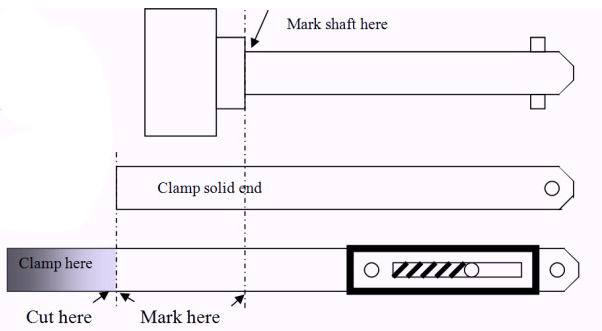
Step 2 - Mark on the existing shaft, the point the shaft fits into the circuit breaker/isolator.
Step 3 - Remove existing extension shaft and place beside new retrofitting shaft as shown. Mark and cut accordingly.
Step 4 – De-burr and spray cut surface with rust proof paint
Step 5 – Re-insert shaft into circuit breaker with mark from step one in line with the face of the circuit breaker (where originally marked) This is important to ensure maximum movement in each direction.
Step 6 – ALWAYS ensure JK Jigger aligns with isolator handle when the handle & isolator are both in the same position i.e. both ON or both OFF.
Step 7 – Fix the label with screws & nuts provided above or beside isolator handle on outside of door to complete installation.
Step 8 – Check again that the handle is not already damaged, that the JK Jigger is aligned as the door is closed on to it, with handle & isolator in both corresponding On or both Off positions and the handle works to switch the isolator as designed, before leaving the work site
Step 9 – Periodic maintenance to check alignment with handles and free action of moving parts is recommended, Lubricate if needed with INOX or Lubricant of similar quality and properties as required.
Tools and accessories that may be required:
Cordless Drill and Grinder
32mm Hole saw or 32mm Hole punch
4 and 6mm Drill bits
5mm round file
Rust proof Paint
Note – Misalignment can sometimes be corrected with the fine adjustment of the 2 grub screws securing the shaft. The C/B switch plate which the shaft fits into on the face of the circuit breaker may, in extreme cases, also need to be replaced, as wear and tear in a harsh environment may allow the shaft to sag more than normal at its furthest point. In some cases it may be quicker and easier to remove the isolator handle and see where the shaft is positioned in relation to the centre of the isolator Handle hole. In Both the ON and OFF positions. The isolator handle hole may need to be moved slightly to ensure JK Jigger aligns with the centre of the isolator handle on the door. A template has been supplied above to suit common isolator handles if holes need to be relocated.
DISCLAIMER
Eagle Alternatives Pty Ltd has provided the above installation procedures to ensure that the Blast Suppressor is correctly fitted and will operate correctly
Eagle Alternatives PTY LTD is not liable for any improper or incorrect use of its goods arising from, or in relation to, any failure to install or use the goods in accordance with the instructions provided or in relation to any abuse, misuse, unauthorised repair or modifications or damage to the goods from any cause.
Warranty claims must be notified within 6 months of purchase and the goods returned with proof of purchase.
Eagle Alternatives Pty Ltd will refund the price of goods or repair or replace them, as it decides, if the goods have any material or manufacturing defect, natural wear and tear is not included.


